Search This Blog

Tuesday, 12 April 2011

Quadrupole Mass Spectrometers

Principal of Operation
A quadrupole field is formed by four electrically conducting, parallel rods(shown in below figure). Opposite pairs of electrodes are electrically connected. One diagonally opposite pair of rods is held at +Udc volts and the other pair at -Udc volts.

                                            
An rf voltage supplies a signal(+V Cos wt) to first pair of rods and (-V Cos wt) to second pair of rods, which appear as oscillating hyperbolic potentials between the four rods. Ions from the ion source are injected into the quadrupole through a circular aperture. As the ions moves down the quadrupole, they undergo transverse motion in x- and y- planes.

The dc electric fields tend to focus positive ions in the positive plane and defocus them in the negative plane. The ions exhibit oscillations with increasing amplitudes until they finally collide with the electodes and become neutral particles. The lighter the ion in mass, the smaller the number of cycles before it is collected by the electrode.

By controlling the ratio Vdc/Vrf, the field can be controlled which allows to pass ions of only one m/z ratio down the entire length of the quadrupole. By simultaneous ramping the dc and rf fields, ions of various m/z ratios are allowed to pass through the mass filter to the detector and an entire spectrum can be produced.
 
The operation of a quadrupole mass analyzer is usually treated in terms of a stability diagram that relates the applied DC potential (U) and the applied RF potential (V(t)) and the RF frequency (omega) to a stable vs. unstable ion trajectory through the quadrupole rods. :

                                  
The ions are passed within a 60ocone around the axis, therefore does not require focusing slits. Increasing the rod length (5-20 cm) increases the resolution. If the rf frequency is increased, the lenght of the analyzer can be reduced. Rod diameters are also a factor: increasing the rod diameter increases the sensitivity by a large factor, whereas decreasing the diameter increases the mass range.

Monday, 11 April 2011

Time-of-Flight Mass Analyzers

Principal of Operation

A linear-field reflectron allows ions with greater kinetic energies to penetrate deeper into the reflectron than ions with smaller kinetic energies. The ions that penetrate deeper will take longer to return to the detector. If a packet of ions of a given mass-to-charge ratio contains ions with varying kinetic energies, then the reflectron will decrease the spread in the ion flight times, and therefore improve the resolution of the time-of-flight mass spectrometer.


Linear
A time-of-flight mass spectrometer uses the differences in transit time through a drift region to separate ions of different masses. It operates in a pulsed mode so ions must be produced or extracted in pulses. An electric field accelerates all ions into a field-free drift region with a kinetic energy of qV, where q is the ion charge and V is the applied voltage. Since the ion kinetic energy is 0.5mv2, lighter ions have a higher velocity than heavier ions and reach the detector at the end of the drift region sooner.

Recall that the kinetic energy of an ion leaving the ion source is:
K.E. = eV
1/2 mv2 = eV


The ion velocity, v, is the length of the flight path, L , divided by the flight time,t:
n = L / t
Substituting this expression for v into the kinetic energy relation, we can derive the working equation for the time – of –flight mass spectrometer
m/e = 2Vt2 / L2
or, rearranging the equation to solve for the time-of-flight: 


Reflectron
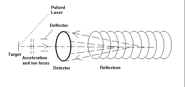
The ions leaving the ion source of a time-of-flight mass spectrometer have neither exactly the same starting times nor exactly the same kinetic energies. Various time-of-flight mass spectrometer designs have been developed to compensate for these differences. A reflectron is an ion optic device in which ions in a time-of-flight mass spectrometer pass through a "mirror" or "reflectron" and their flight is reversed.
A linear-field reflectron allows ions with greater kinetic energies to penetrate deeper into the reflectron than ions with smaller kinetic energies. The ions that penetrate deeper will take longer to return to the detector. If a packet of ions of a given mass-to-charge ratio contains ions with varying kinetic energies, then the reflectron will decrease the spread in the ion flight times, and therefore improve the resolution of the time-of-flight mass spectrometer.


Double- Focusing Sector Spectrometers:

Magnetic /electrostatic sector instruments use magnetic and electric fields to disperse ions according to their momentum and translational energy. Like the magnetic sector, the electric sector applies a force perpendicular to the direction of ion motion, and therefore has the form of an arc.  


The dependence of mass-to-charge ratio on the electric and magnetic fields is easily derived as below. All ion formed in the ion source are accelerated to a kinetic energy, T of
T = eV = mn2 / 2

Solving for the velocity v we get: 


From the Lorentz force law, the magnetic field applies a force evB that must be equal to the centripetal force mv**2/r as the ions move in an arc through the magnetic sector: 
e vB =  m υ 2  / r

Substituting for v, we arrive at the working equation for a magnetic sector mass spectrometer: 
m/e = B2r2 / 2V

Therefore ions are accelerated out of the source and are collimated into a narrow beam by a set of slits. As the ions pass through the electrostatic sector, they are dispersed according to their translational energy. Only those ions that have the correct translation energy pass through the slits at the end of the electrostatic sector. Finally the magnetic sector disperses the ions according to their mass to charge ration.
A mass spectrum is obtained by scanning the accelerating voltage (electric field) while hold B constant and scan V  to bring ions with different m/z ratios sequentially to focus at the detector.

Magnetic -Deflection or Sector Mass Analyzer:

In a magnetic deflection mass spectrometer, ions leaving the ion source are accelerated to a high velocity. The ions then pass through a magnetic sector in which the magnetic field is applied in a direction perpendicular to the direction of ion motion. When acceleration is applied perpendicular to the direction of motion of an object, the object's velocity remains constant, but the object travels in a circular path. Therefore, the magnetic sector follows an arc; the radius and angle of the arc vary with different ion optical designs.


A magnetic sector alone will separate ions according to their mass-to-charge ratio. Only ions of a single m/z value will have the proper trajectory leading to the exit slit ahead of the detector. By changing the magnetic field strength, ions with differing m/z values are brought to focus at the detector slit.

The ions velocity ‘υ’, in the magnetic field is given by


Limitation:

In a single-focusing magnetic sector instrument there is a lack of uniformity of ion energies, since the accelerating potential experienced by an ion depends on the region at which it is formed in the ionization chamber. The resulting spread in ionic energies produces a spread in their radii of curvature in the magnetic field. The result is peak broadening and low to moderate resolution.

½ m υ 2  =zV
However, the resolution will be limited by the fact that ions leaving the ion source do not all have exactly the same energy and therefore do not have exactly the same velocity.

MALDI (MATRIX-ASSISTED LASER DESORPTION IONIZATION)

Matrix-assisted laser desorption ionization a laser beam is fired at the crystals in the MALDI spot. The matrix absorbs the laser energy and it is thought that primarily the matrix is ionized by this event. The matrix is then thought to transfer part of its charge to the sample molecules , thus ionizing them while still protecting them from the disruptive energy of the laser. Ions observed after this process consist of a neutral molecule [M] and an added or removed ion. Together, they form a quasimolecular ion, for example [M+H]+ in the case of an added proton, [M+Na]+ in the case of an added sodium ion, or [M-H]- in the case of a removed proton.


The matrix consists of crystallized molecules, of which the two most commonly used are 3,5-dimethoxy-4-hydroxycinnamic acid, α-cyano-4-hydroxy Cinnamic acid  A solution of one of these molecules is made, often in a mixture of highly purified water and an organic solvent such as acetonitrile or ethanol.

ELECTROSPRAY IONIZATION

In electrospray ionization, a liquid is pushed through a very small, charged and usually metal, capilary. This liquid contains the substance to be studied, the sample, dissolved in a large amount of solvent, which is usually much more volatile than the sample. Volatile acids, bases or buffers are often added to this solution too. The sample exists as an ion in solution either in its anion or cation form. Because like charges repel, the liquid pushes itself out of the capillary and forms an aerosol, a mist of small droplets about 10 μm across.


The aerosol is at least partially produced by a process involving the formation of a Taylor cone and a jet from the tip of this cone. An uncharged carrier gas such as nitrogen to evaporate the neutral solvent in the droplets. As the solvent evaporates, the analyte molecules are forced closer together, repel each other and break up the droplets. This process is called Coulombic fission because it is driven by repulsive coulombic forces between charged molecules. The process repeats until the analyte is free of solvent and is a lone ion. In electrospray processes, the ions observed may be quasimolecular ions created by the addition of a proton or cation(Na+).


FAST-ATOM BOMBARDMENT (FAB)

In FAB a high-energy beam of netural atoms, typically Xe or Ar, strikes a solid sample causing desorption and ionization. It is used for large biological molecules that are difficult to get into the gas phase. FAB causes little fragmentation and usually gives a large molecular ion
peak, making it useful for molecular weight determination.

The atomic beam is produced by accelerating ions from an ion source though a charge-exchange cell. The ions pick up an electron in collisions with netural atoms to form a beam of high energy atoms.